Adapted with permission from Revolution Education
Hello and welcome! This is an informal description of a project I got into, to build an interface to collect measurements of light intensity, temperature and relative humidity using the PICAXE-08M microcontroller (µC) and a computer's serial port. I needed to measure these parameters pronto for my thesis project and, in haste, I hacked this thing together, or rather glued it together (quite literally!). Please e-mail me if you have questions or comments. cirelli $AT! ualberta %DOT& ca
The astute reader will surely ask why in the world I didn't use something more sensible, something with higher resolution and/or more legs. 'Tis indeed a good question but as I mentioned, I needed something right away at the time, and all I had lying around were a bunch of 08M's and those nifty proto board kits.
Resolution is not a huge deal actually; the 08M comes with a 10-bit ADC, and averaging over a changing variable will give you an improved resolution. The number of pins was actually a problem and that's why I'm writing this. This is very cheap and easy to build so I hope it is of use to somebody. It certainly served me well.The fine print: I only graze the surface of electronics, even as a hobby. Many of the things described here may not be ``orthodox'', feel free to provide feedback! Above all, when in doubt, consult with a professional or proceed at your own risk. The documentation for the hardware described in this page is released under the Creative Commons (CC) BY-NC-SA 3.0 license and it is applicable to the amalgam of components (the design(s)) that constitute the end product(s), but not to the components themselves, whose designs are the intellectual property of their manufacturers or otherwise copyright-holders as indicated in each product's data-sheet. The firmware and software to run the hardware are released under the GNU General Public License v3.0. The information provided here as well as the software is distributed in the hope that it will be useful, but WITHOUT ANY WARRANTY; without even the implied warranty of MERCHANTABILITY or FITNESS FOR A PARTICULAR PURPOSE. Please see the appropriate licenses (as mentioned above) for more details.
There, with the formalities out of the way, let's proceed...
The PICAXE-08M is a wonderful little chip base on the PIC12F689 by Microchip. Other websites cover it in more detail that I ever could so I won't reiterate them. I will say that the documentation is great and if you are unfamiliar (or familiar!) with it, I encourage you to download the manuals from Rev-Ed.
The concept here is simple:
(1) Computer <---> (2) Serial interface (master) <---> (3[a]) Sensor package (slave, up to 3)
There are, of course the various bits of software needed to make all this "go" (listed at the end of this document).
You've got (1) well covered, so we'll dive right into the master interface (2)
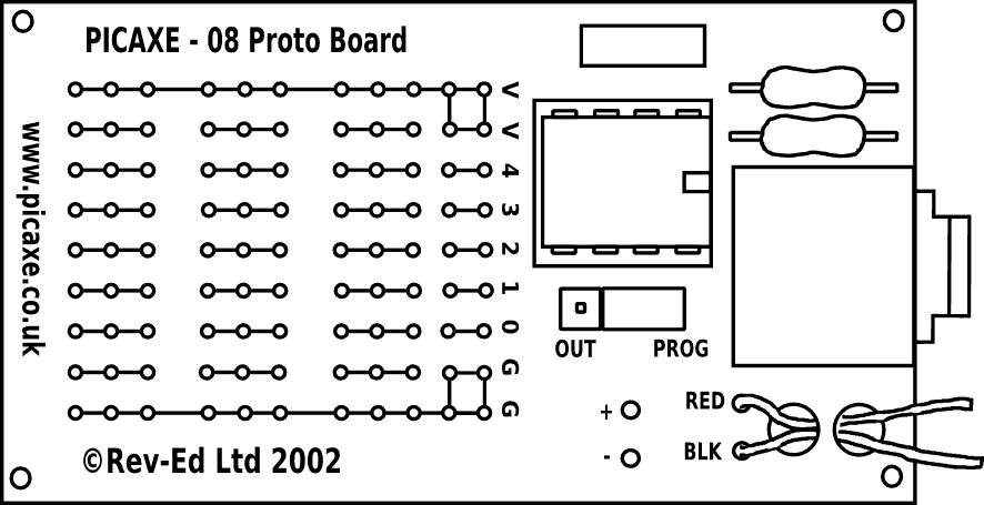
If you don't know what the protoboard for the 08m looks like, here it is:
Adapted with permission from Revolution Education
These boards are incredibly useful and versatile (unlike the boards for bigger chips, IMHO, as of 2010). The problem here is of course that 8 legs were not enough although in hindsight careful timing and more elaborate firmware might have solved the problem. Nevertheless, here is a tip for lazy (non)programmers like me:
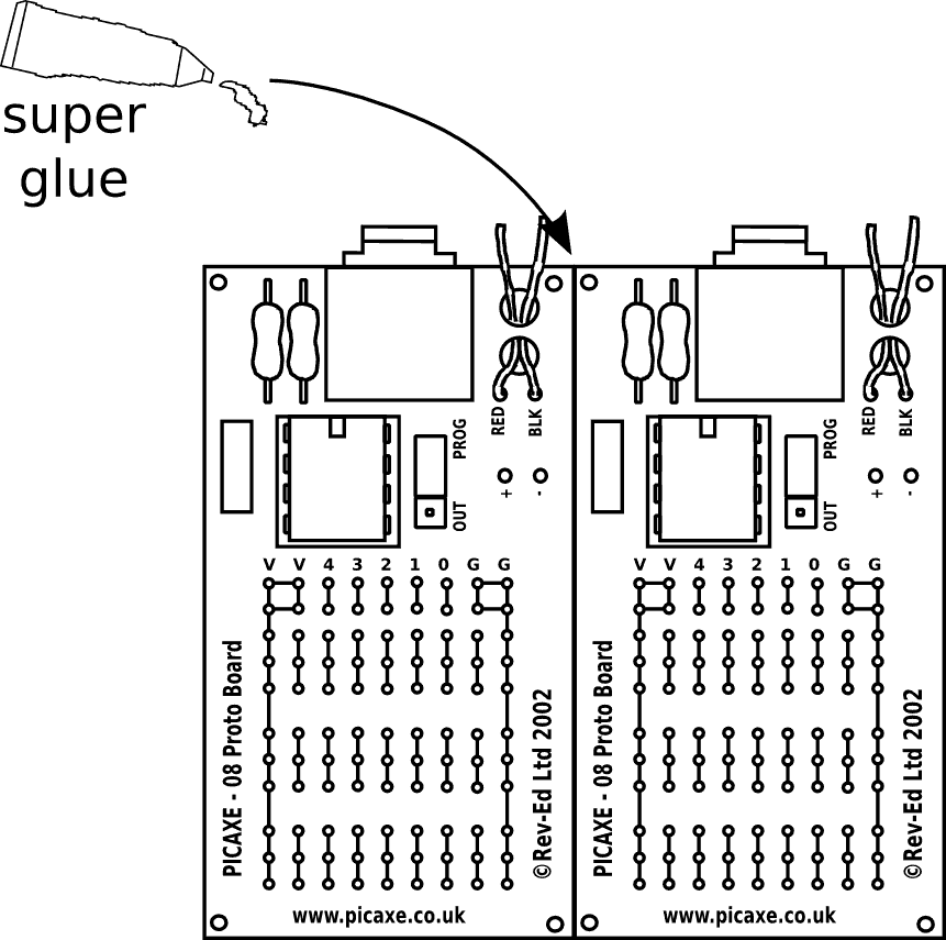
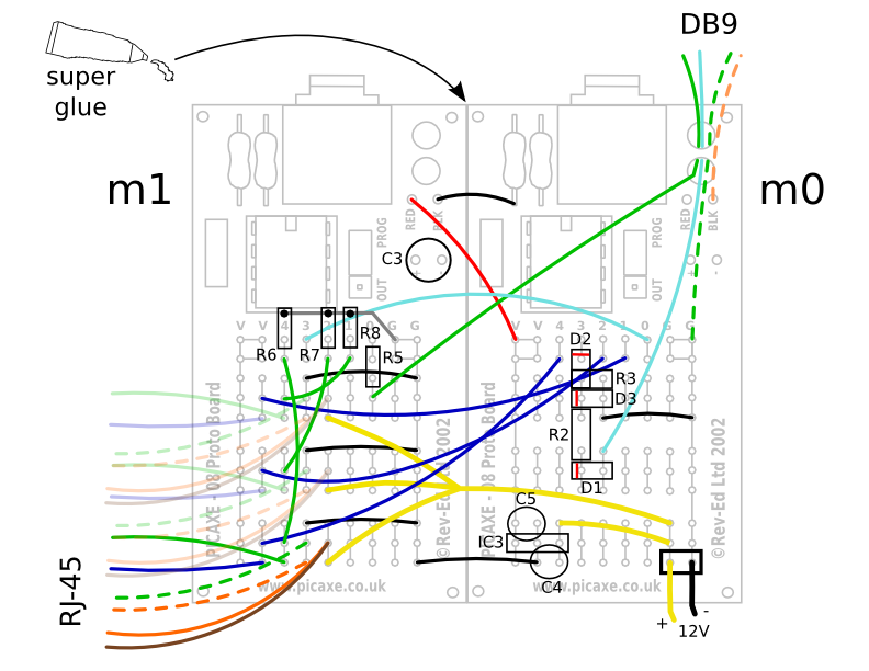
Presto!A “16-legged 08m”! (more like a 14-legged really). In any case, glue alone is not going to do it. So here is what I did. The complete diagram is below, but you can “peel off layers” by clicking the appropriate labels below the drawing.
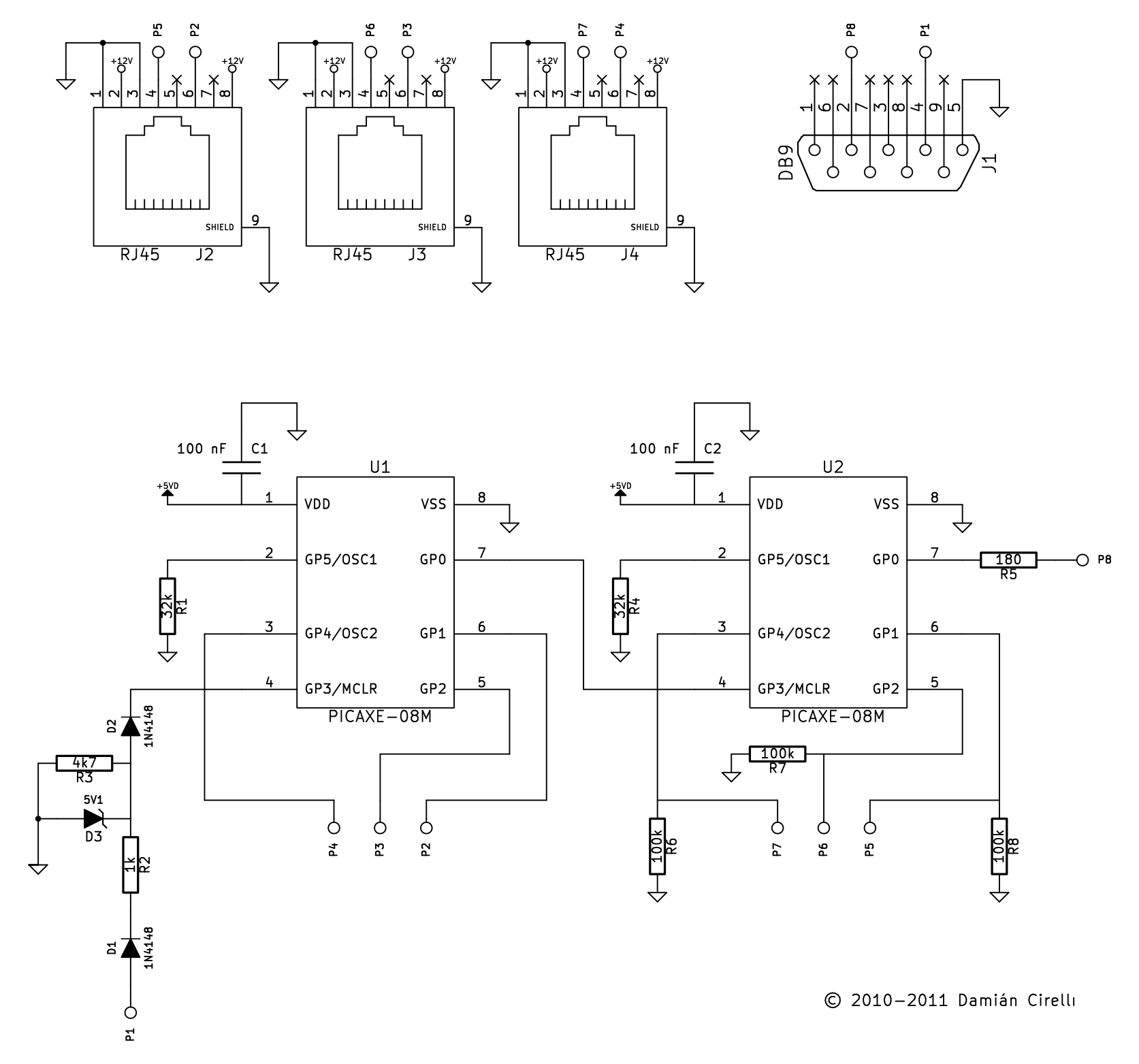
Not a lot of passives here, but surely a lot of cables. Some components have been omitted in the schematic. C3 is an optional 100μF capacitor which I would recommend. IC3, C4 and C5 are not in the schematic either tough it is implied since the RJ-45 connectors have +12V connections and the chips show +5V in the power pin. IC3 is clearly a regulator but since that is quite flexible in how you implement it I left it out. I chose the L4931 because it seemed like a good fit. At any rate, it is important to have +12V available on the CAT-5/6 cables which connect to the slaves because they need to power a fan on the slaves' side. Also note that a couple of components are in the schematic but not in the drawing. The small capacitors for example are part of the protoboard kit so they are outlined in the drawing (rectangle to the left of the chip) but not referenced, just FYI.
The little circuitry between P1 and U1 is a horrible hack, I know. Read the disclaimer, I told you I wasn't well versed in electronics! It will prevent the potential from going below 0V since the DTR line used to generate the interrupt can range from -3V to -12V when toggled low (depending on the computer). Definitely not a good idea for the chip. There is surely a more elegant way to deal with that (some fancy TTL level converter?)
And that's the master interface. The nice thing about the proto-boards also, is that they allow for programming the chips in place simply by moving a jumper. Note that the chips are labelled m0 and m1 in the drawing and they correspond to master0 and master1 in the firmware source. Both masters will expect an interrupt. Typical operation (in pseudocode) would be:
      !Interrupts are LOW. i.e. inputs go from normally high (+5V) to low (0V) to generate response

      m0: wait for interrupt; idle waiting for input3 to be low
      m0 <- receive interrupt; input3 was pulled low (by computer)
      m0: send interrupt -> m1; pull output0 low
      m0: send interrupt -> s1,s2,s3; "distribute" interrupts to *potentially* connected slaves
      m0: wait for interrupt; m0's job is done and goes back to waiting, m1 takes over...
      ---
      m1: wait for interrupt
      m1 <- receive interrupt; m0 has sent an interrupt on m1's input3
      m1: do a "presence check"; check which slaves are plugged-in
      m1 <- receive data from one slave; expect data on first "active" input
      m1 -> send data to computer
      m1 <- receive data from another slave; if no slave is connected create blank data
      m1 -> send data to computer, even if blank
      m1 -> send '!\n'; exclamation-newline is interpreted as EndOfLine by the program
And that's the job of the master interface: shuttle data between the serial port and the slaves. What is important about this is the use of interrupts to initiate readings. This allows a rudimentary but quite good (within 1-3 s) synchronisation between instruments. Since this was designed to work in synchrony multiple balances measuring plant transpiation, both programs (the balance-reading and the one that reads these sensors) need to read their respective instruments as close to simultaneously as possible.
The sensor package consists of yet another 08m chip plus the actual sensors. In this case, the μC is interrupted by the master interface and it goes on to reading the digital thermometer (DS18S20) and the humidity (HIH4000) and light (gallium photodiode) sensors. Both the RH and photodiode have analog voltage outputs so the 08m reads them thourgh its 10-bit ADC inputs. The thermometer is the exception because it uses the 1-wire protocol which the 08m can use to receive a 12-bit temperature reading. All the readings require further processing but that is not done by the μC. Instead it sends all the raw values to the master interface and the master interface sends the raw values of all connected slaves to the computer. We can easily process the data in the computer instead, which is much easier and keeps the firmware much simpler.
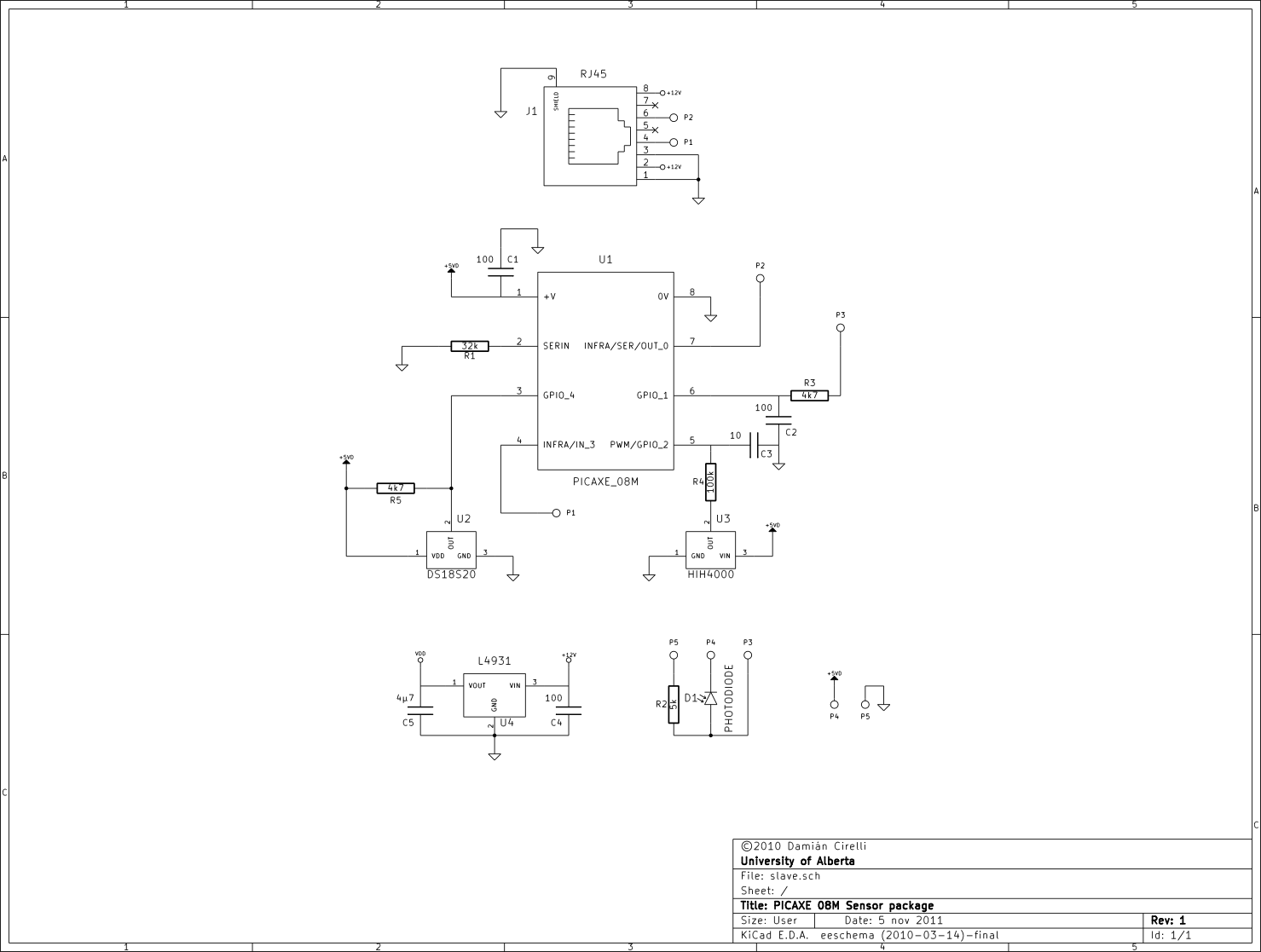
Sensor package schematic (click for full size)
The photodiode should be connected with a shielded (and short) cable since it has to live ex-situ. For maximum performance it should include a hemispherical diffuser. How one calibrates this will depend on a number of things. Because I had a LI-250A PAR meter from LI-COR I used it to build a calibration curve with a full-spectrum light (varying the distance to the source). It turned out to have a pretty linear relationship but this will probably change with photodiode type. The sensitivity can be adjusted by changing R2 (larger values will make it more sensitive but will go out of range quickly). Best to experiment according to one's needs.
As always it is advisable to shield the temperature sensor from radiation. The HIH4000 is particularly sensitive to light so it too needs to be shielded. My approach was to house the entire board inside a PVC pipe with elbows. The pipe and elbows were spray-painted in matte-black. One end of the pipe was fitted with an 80-mm computer fan which pulls air from the other end (so we don't blow on the components). This is why it is handy to have the +12V supply on the cable that goes to slave, so the fan can be powered directly from the board. The outside of the PVC pipe can be further insulated if you are paranoid (like me!) about it heating up in the sun... some foam and alluminum foil should do the trick ;-)
The files need heavy documentation which I will add as I have time. The interrupts are a bit over the top in that there is a double-check that the interrupt was indeed generated legitimately. I may do away with this, feel free to submit firmware improvements!
Thanks for visiting!